

| Height | 6 feet 2⅜ inches (1890 mm) |
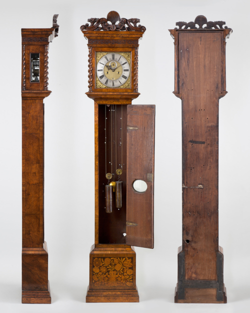
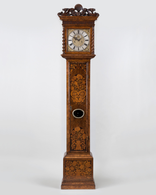
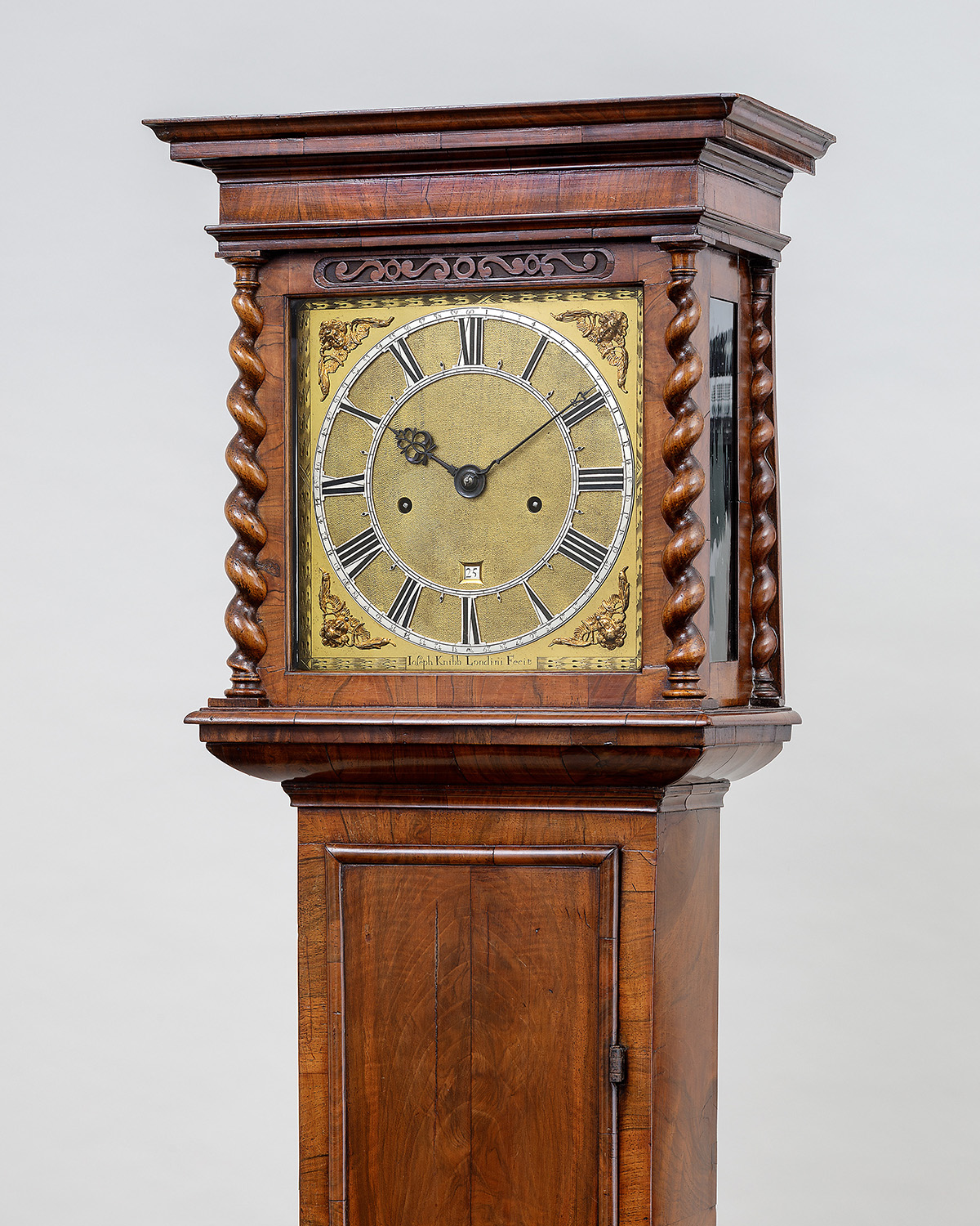
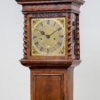
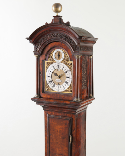
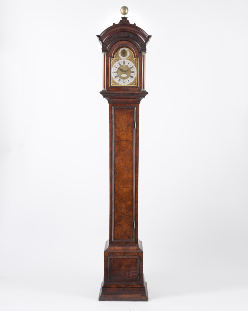
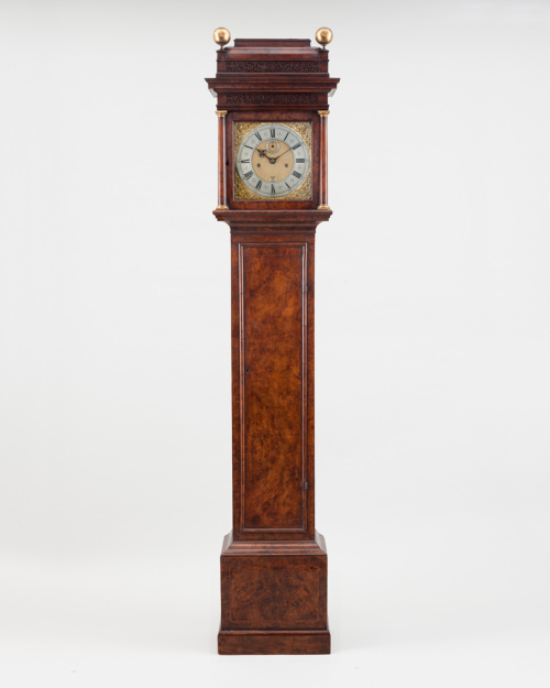
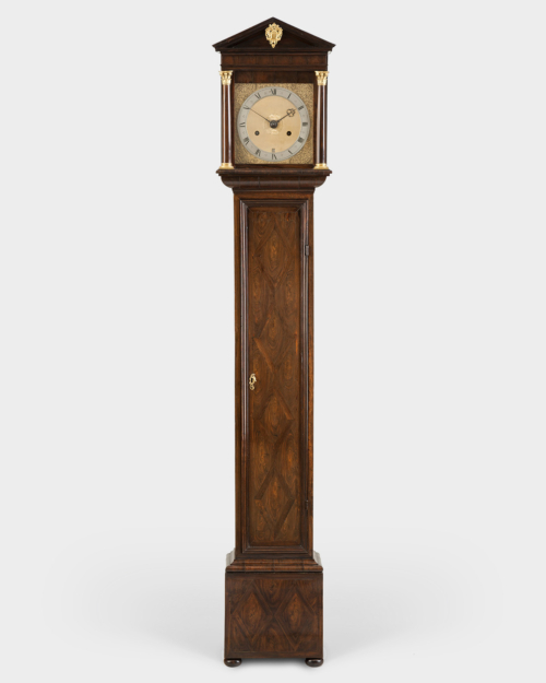
| Case | The case veneered in figured walnut and cross-grain walnut mouldings onto rare cariniana wood carcassing. The rising hood with delicate walnut cornice mouldings with a solid freize over walnut Solomonic reflective columns, with integral turned capitals and bases, flanking the dial aperture, with matching quarter columns to the rear hood uprights. The pierced walnut sound fret unusually inset into the rail of the dial aperture between the columns. The trunk with convex throat mouldings, above the trunk door framed by half-round cross-grain mouldings and veneered with eight book-matched sections. The cross-grain cavetto/ovolo base moulding crowning the cross-banded plinth with oyster-cut walnut veneers, on later walnut bun feet. |
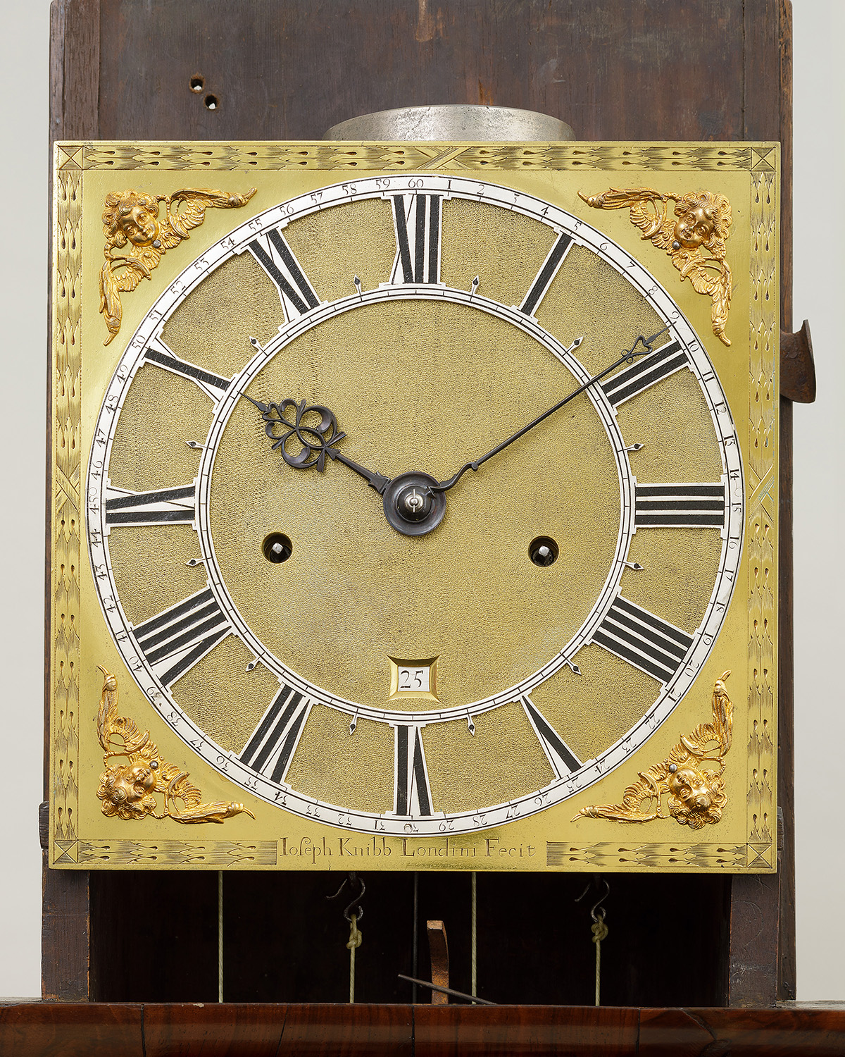
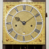
| Dial | The 10 inch (254 mm) square fire-gilded brass dial with a double-wheatear engraved border, signed within to the lower edge Joseph Knibb, Londini Fecit. The fine central matting, overlaid by a silvered brass skeletonized chapter ring, with every Arabic minute numbered outside the pierced Roman chapter with simple dot half-hour marks, and inset with a chamfered and shaped date aperture above VI. Knibb’s early pattern gilt-brass winged cherub head corner spandrels, with typical well-pierced and sculpted blued steel hands. The dial fixed with four dial feet with screw-fixed latches. |
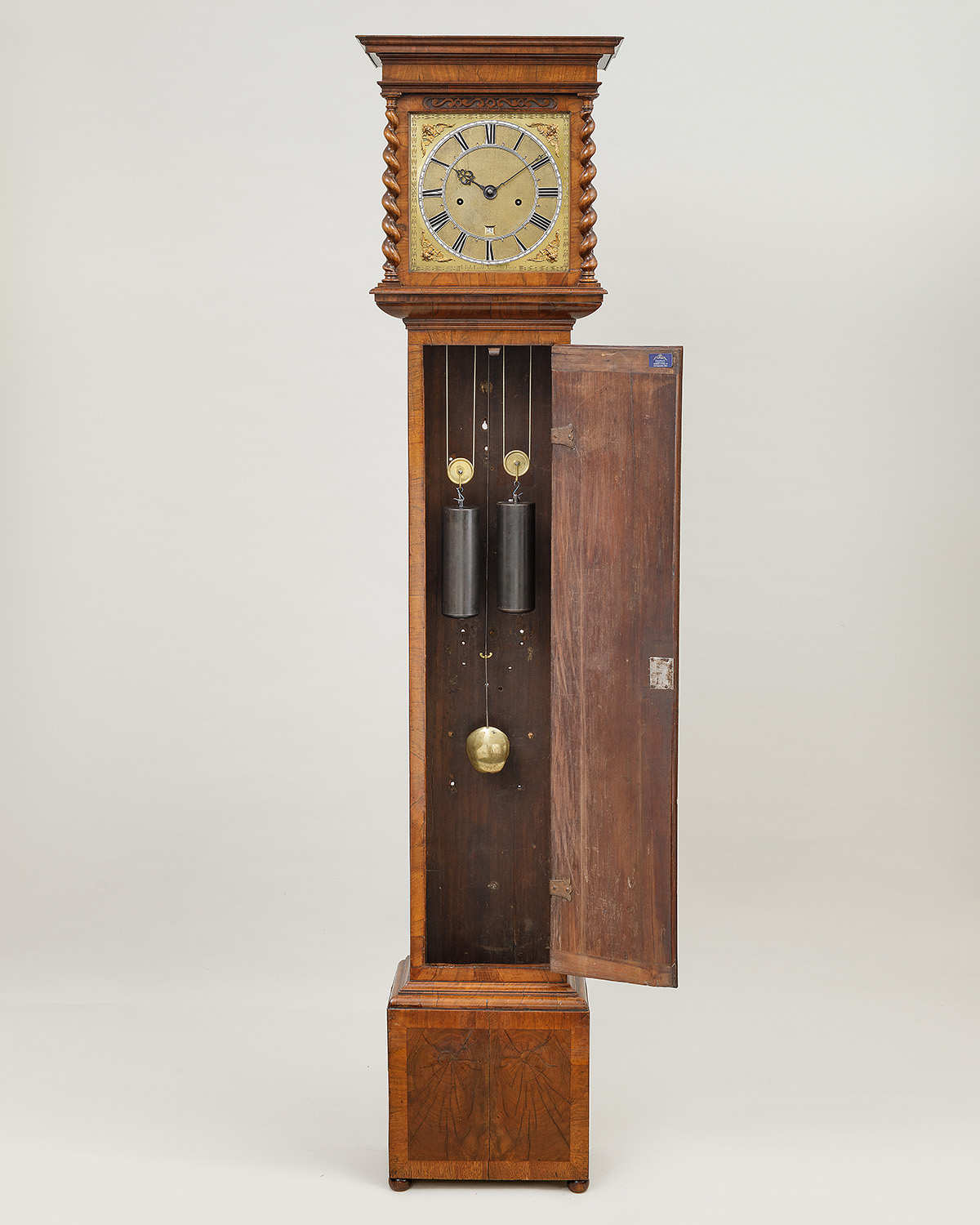
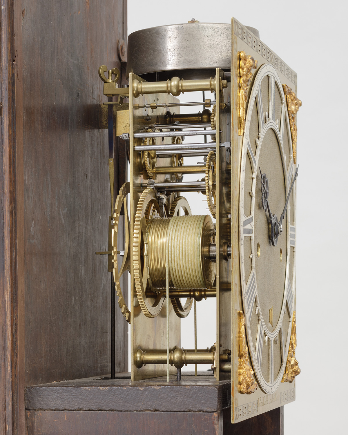
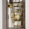
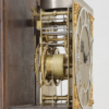
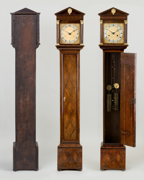
| Movement | The typically light and fine Knibb movement with six finned knopped pillars, with screw-fixed latches to the frontplate. The going train with anchor escapement and pallet cut-out in the backplate, the pallet-arbor cocked and the pendulum spring suspension with fine adjustment butterfly-nut above, the brass rod pendulum with a further wing nut for coarse adjustment via the threaded lenticular bob. The strike train governed by a large outside hour and quarter countwheel mounted to the greatwheel/barrel arbor, with a typical Knibb pump-and-link hammer system; sounding the quarters on the smaller bell; while the hours are struck on the larger ‘porkpie’ bell mounted above. The whole fixed by seatboard screws through the bottom pillars, and further secured by a bracket to the case backboard. |
| Duration | 8 days |
| Provenance | Sotheby’s, 15th June 1994, lot 479; |
| Comparative Literature | Lee, The Knibb Family, Clockmakers, 1964 pl.34, 49 and col. pl.5; |
| Literature | Garnier & Hollis, Innovation & Collaboration, 2018, (illus.) p.282-3 |
| Escapement | Anchor with butterfly-nut fine adjustment to the spring suspension |
| Strike Type | Outside combined hour and quarter countwheel mounted on the greatwheel arbor |
Exhibit № 22. Joseph Knibb, London, Circa 1680
A fine Charles II two-train quarter striking walnut longcase clock with skeletonised chapter ring
£95,000
This clock epitomises Knibb’s ingenuity for complex countwheel striking, but Knibb went further and skeletonised the chapter ring, which would have come at considerable extra cost, as the requirement for close-edged dial matting was both difficult and time consuming. As a result, skeleton chapter rings were usually reserved solely for his best productions. RA Lee in The Knibb Family, Clockmakers, noted: Few makers in London ever used them, Clement, Barrow, Dingley, Tompion, Seigniour, Henry Jones and Joseph Knibb.
The case utilises cariniana as its carcass wood and less than 15 examples are currently recorded. Most are associated with movements produced by members of the Knibb family (Joseph, Peter and John), although cases housing other makers’ movements have also been found, such as the two earliest examples by Simon Bartram and Hilkiah Bedford (see exhibits no.5 and no.13).
Knibb’s single train hour and quarter striking countwheel system
This system strikes the quarters at 15, 30 and 45 minutes past, followed by the hour on the hour, it has two bells but uses a single countwheel with a double-sided pinwheel within the plates, in this instance a hammer lift assembly is pumped, backwards and forwards by the minute wheel to bring the quarter and hour bells into play as required. The countwheel is subdivided by raised, increasing arc segments for the twelve hours but also subdivided again between each hour by the three quarter arc segments.
The minute wheel rotates once per hour and has 4 equally spaced pins for every quarter and the system is activated in passing. At each quarter a pin lifts the release lever on the frontplate, this is mounted onto the warning arbor between the plates that has the warning piece attached internally and a lifting piece to lift the countwheel detent arbor, which is placed directly above and parallel. The countwheel detent arbor has the hoop wheel detent fixed internally and the countwheel detent attached externally on the backplate, which at this stage, is locked and seated in one of the hour divisions.
At a minute or two before the quarter, the release lever is raised by one of the pins on the minute wheel and the warning arbor lifting piece engages with the countwheel detent arbor above. This, in turn, raises the hoop wheel detent releasing the hoop wheel. The warning wheel runs for about half a turn until stopped by a pin on its rim engaging with the warning piece and putting the system on ‘warning’ to allow the train to release exactly on the quarter (or hour). The minute wheel continues to turn and, on the quarter (or hour), the pin passes and the release lever drops.
Meanwhile, the minute wheel cam constantly pumps the hammer lift assembly, controlling which bell comes into play, so that on the quarters the quarter hammer tail engages with the rear side of the pinwheel, while on the hours the hour hammer tail engages with the front side of the pinwheel. Thus the rotating pinwheel gathers the required tail on the hammer assembly, lifting the hammer, which then strikes the bell as the tail passes and drops off each pin. At the same time, the hoop wheel in the strike train rotates and the hoop wheel detent (mounted on the countwheel detent arbor) falls into the gap therefore checking the state of the countwheel after each blow. When the detent finds the next slot in the countwheel it drops into the hoop gap and locks the hoop wheel, stopping the strike train from turning.
Product Description
This clock epitomises Knibb’s ingenuity for complex countwheel striking, but Knibb went further and skeletonised the chapter ring, which would have come at considerable extra cost, as the requirement for close-edged dial matting was both difficult and time consuming. As a result, skeleton chapter rings were usually reserved solely for his best productions. RA Lee in The Knibb Family, Clockmakers, noted: Few makers in London ever used them, Clement, Barrow, Dingley, Tompion, Seigniour, Henry Jones and Joseph Knibb.
The case utilises cariniana as its carcass wood and less than 15 examples are currently recorded. Most are associated with movements produced by members of the Knibb family (Joseph, Peter and John), although cases housing other makers’ movements have also been found, such as the two earliest examples by Simon Bartram and Hilkiah Bedford (see exhibits no.5 and no.13).
Knibb’s single train hour and quarter striking countwheel system
This system strikes the quarters at 15, 30 and 45 minutes past, followed by the hour on the hour, it has two bells but uses a single countwheel with a double-sided pinwheel within the plates, in this instance a hammer lift assembly is pumped, backwards and forwards by the minute wheel to bring the quarter and hour bells into play as required. The countwheel is subdivided by raised, increasing arc segments for the twelve hours but also subdivided again between each hour by the three quarter arc segments.
The minute wheel rotates once per hour and has 4 equally spaced pins for every quarter and the system is activated in passing. At each quarter a pin lifts the release lever on the frontplate, this is mounted onto the warning arbor between the plates that has the warning piece attached internally and a lifting piece to lift the countwheel detent arbor, which is placed directly above and parallel. The countwheel detent arbor has the hoop wheel detent fixed internally and the countwheel detent attached externally on the backplate, which at this stage, is locked and seated in one of the hour divisions.
At a minute or two before the quarter, the release lever is raised by one of the pins on the minute wheel and the warning arbor lifting piece engages with the countwheel detent arbor above. This, in turn, raises the hoop wheel detent releasing the hoop wheel. The warning wheel runs for about half a turn until stopped by a pin on its rim engaging with the warning piece and putting the system on ‘warning’ to allow the train to release exactly on the quarter (or hour). The minute wheel continues to turn and, on the quarter (or hour), the pin passes and the release lever drops.
Meanwhile, the minute wheel cam constantly pumps the hammer lift assembly, controlling which bell comes into play, so that on the quarters the quarter hammer tail engages with the rear side of the pinwheel, while on the hours the hour hammer tail engages with the front side of the pinwheel. Thus the rotating pinwheel gathers the required tail on the hammer assembly, lifting the hammer, which then strikes the bell as the tail passes and drops off each pin. At the same time, the hoop wheel in the strike train rotates and the hoop wheel detent (mounted on the countwheel detent arbor) falls into the gap therefore checking the state of the countwheel after each blow. When the detent finds the next slot in the countwheel it drops into the hoop gap and locks the hoop wheel, stopping the strike train from turning.
Additional information
| Dimensions | 5827373 cm |
|---|
Related products
-
Anthony Banister, London Circa 1730
Sorry Sold -

The Gardener’s Tompion No.325 Circa 1699
Sorry Sold -
Edward East, London. Circa 1668.
£330,000 -